
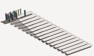
Strip layout design concept for metal stamping
All metal stamping designs should start with the basics. A solid foundation is required with both a visual and technical guide to progress further. The strip layout is the starting point of a metal stamping design which is the foundation or plan to manufacture and build the actual tool.The strip layout design has several purposes. Once complete, it gives a visual representation to the manufacturing facility and to the client to have a good idea how the tool will work and how each progression or step will be made once the strip or coil is inserted into the die. The stamping can then begin.
The proper tool and die design of a strip layout gives a piece of mind to the tool and die designer to proceed in the right direction. It is insurance for the end user or those who finance the project and want to be sure that their investments are in good hands with the tool working efficiently for a long period of time without breaking down. This is what it is all about. The sole purpose of a metal stamping tool is to produce as many identical high quality parts as possible at the shortest amount of time without stopping. Every time the tool requires maintenance and is not producing, it takes money away and becomes less efficient.
A good metal stamping die starts with a solid foundation, a good strip layout that gives the chance to eliminate future nuances, and to build world class tools that you can count on.